| |
|
The
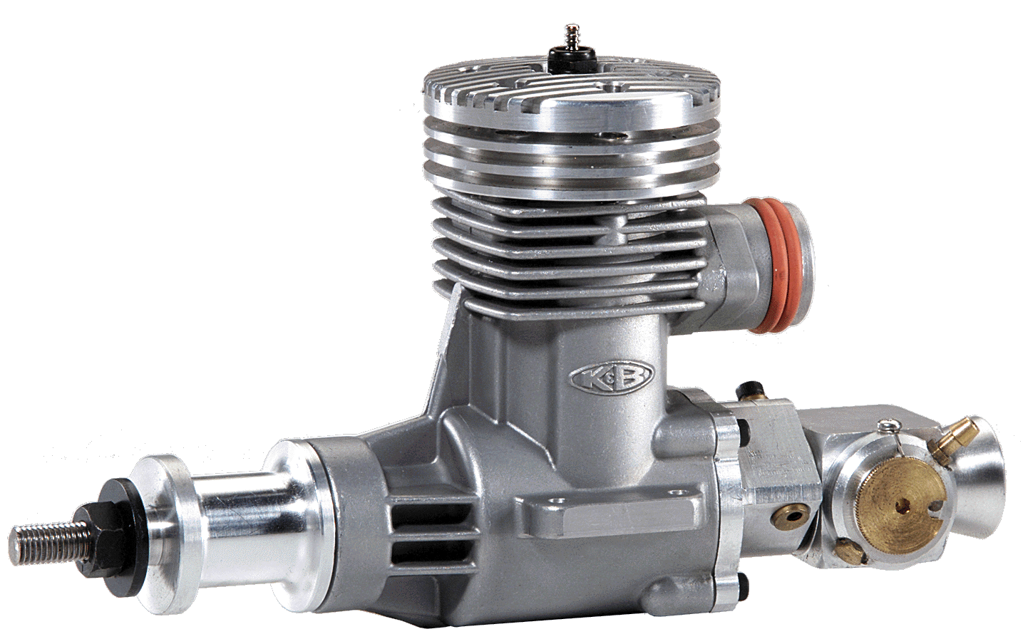
K&B .45 DF is a high-performance engine, designed especially
for ducted fan models.
It is an improved version of our previous, highly successful
engine, known throughout the world
for its power and proven reliability, and will provide countless
hours of
sport or competition performance if properly handled and maintained.
|
| |

Part
No. 4825
|
| SPECIFICATIONS
|
| Displacement
|
.4539
Cu. In. (7.44cc) |
| Bore |
.850
(21.6mm) |
| Stroke |
.800
(20.3mm) |
| R.P.M. |
2,000
- 25,000 |
| Power
Output |
2.75
HP @ 25,000 |
| Weight |
15.8
Oz. (448g). |
|
|
| |
|
WARNING
|
|
PLEASE
READ ALL SAFETY
INSTRUCTIONS! Failure to read, understand and follow
these instructions could result in personal injury and/or
property damage to yourself or others.
Take
a few moments to familiarize yourself with the various parts
of the engine. DO NOT DISASSEMBLE YOUR ENGINE! Doing so will
void your warranty. No exceptions!
|
| |
| |
| |
|
ENGINE
OPERATING NOTES
|
|
GLOW
PLUG
|
| This engine
is designed to use our Long Reach Glow Plug (K&B Part No.
7311). |
| |
|
FUEL
|
| We recommend
15% nitro with 22% oil. A pressurized fuel system must be used
to boost the fuel to the needle valve. Install a pressure fitting
on the tuned pipe, just behind the apex where the cones join.
An in flight mixture control (P/N 9275) is highly recommended
for use with this engine. |
| |
|
IMPORTANT
PRECAUTIONS
|
- Never
place your hand in front of the fan for any reason while
the engine is running.
- Keep
rags, articles of loose clothing, or anything that might
be ingested, well clear of the duct intake.
- Always
start the engine at an idle throttle setting.
- Wear
eye and ear protection.
|
|
MAINTENANCE
|
- MAKE
PERIODIC CHECKS:
After every flight, remove the glow plug and check the coil
condition. If it is broken or badly distorted, replace it.
The glow plug life will be longer when you achieve a good
needle valve setting.
- After
every four flights, check tightness of the engine head and
mounting screws, as well as fan and spinner security.
- After
every twelve flights, check the tuned pipe coupler, and
tightness of the clamps.
|
| |
|
OPERATING
INSTRUCTIONS
|
|
If you
are unfamiliar with this line of carburetors or are a new
modeler, please do not attempt to start the engine until you
have read and understand the following instructions:
1. NEEDLE
VALVE SETUP - Locate an area to install the Remote Needle
Valve Assembly. This assembly must be in the fuel line between
the tank and the carburetor. The line should not exceed five
(5) inches in total length.
2. LINKAGE
SETUP - Notice
the barrel will rotate 360 degrees. Using your radio and trim
functions, set the barrel movement for full open and full
close. IMPORTANT: THE BARREL MUST CLOSE
IN A CLOCKWISE ROTATION. The opening in the barrel
spraybar faces the crankshaft.
|
| |
|
NEEDLE
VALVE ADJUSTMENTS
|
|
Note that
there are two fuel metering adjustments:
1.
HIGH-SPEED NEEDLE VALVE - This
needle valve, located on the remove Needle Valve Assembly,
controls all the fuel that comes to the engine, whether the
engine is running at high, mid-range, or idle speeds. It does
not affect the low speed rich/lean setting. The High Speed
Needle Valve’s main function, however, is to meter the
high-speed fuel mixture.
2.
LOW SPEED and MID-RANGE ADJUSTMENT - The
rich/lean adjustment is controlled by the brass low speed
disk located on the side of the carburetor. Using the allen
wrench provided, turn the disc clockwise to “lean”
the mixture and counter-clockwise to “richen” the
mixture. The rich/lean mixture control is set at the factory
and may require only a fine adjustment for your application.
WARNING: DO NOT RUN THE ENGINE AT A
“LEAN” SETTING.
|
| |
|
NEEDLE
VALVE ADJUSTMENTS - GENERAL
|
|
As a starting
point for the high-speed needle adjustment, completely close
the needle valve (clockwise), then open it (counter-clockwise)
three and a half turns. This setting is an average and may
require further adjustments. For higher altitudes (3,000 -
4,000 feet), close needle valve approximately 1/2 turn.
|
| |
|
PRESSURIZED
SYSTEM
|
|
All
series “94” carburetors must run with exhaust pressure
from the tuned pipe connected to the fuel tank.
|
| |
