|
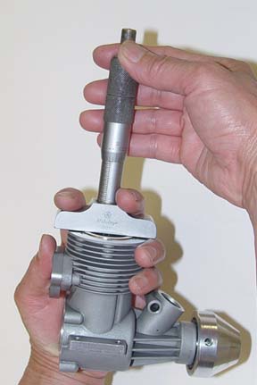
Using the calipers
in this manner will provide an accurate comparison if your
caliper is older or of lower quality.
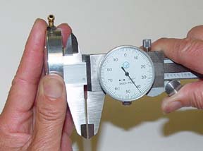
A note on cheap
or junky calipers. If you measure both the depth of the piston
in the cylinder and the protrusion of the head in the same
fashion (the same end of the calipers), it actually doesn't
matter if the caliper zeros properly. Our result will be the
difference between two measurements, so if both measurements
are off .003" the result will be the same.
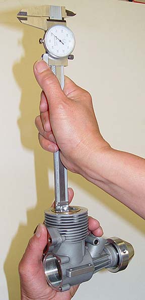
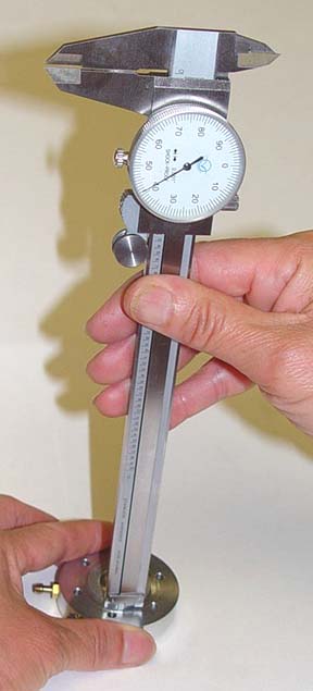
Here our example
again measures .041"
Now do the math...
.062-.041= .021
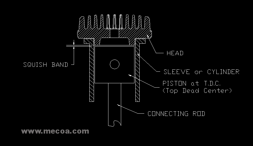
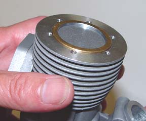
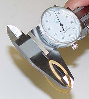
The squish band
is usually set between .016" and .022"
This at the upper
end of the squash band width and the lower end of the compression
spectrum and since this is a larger engine .021 is a good
setting. No head shim is required. This setting can vary with
Nitro content of fuel, exhaust systems, and air density. See
also compression
ratio
|